|
TrackMate Iridium Timing System for R/C Cars
|
Some Pictures From Customers Using TrackMate Iridium |
 |
 |
_small.jpg) |
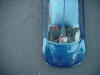
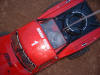
- Transponder
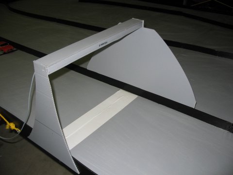
- 1/24 Scale Bridge
- 1/12 Scale
|
_small.jpg) |
_small.jpg) |
 |
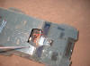
- 1/12 Scale
- Transponder in Xmod
- 1/10 Scale On Road
|
_small.jpg) |
 |
 |
- 1/24 Scale Track
- -
- Off Road
|
 |
 |
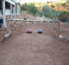 |
- Transponder in 1/10 Off Road
- 1/10 Scale Off Road
- 1/10 Off Road Track
|
-
Easy to install
-
Low Cost complete package
-
Small, thin, sealed and light weight transponders
-
Unique transponder IDs for each member of your RC club
for no hassle race setup
-
Toll free support
-
Supports old and new PCs running Windows 95,98,ME,XP,Vista
-
Connects to Com port or USB (using USB to serial converter)
-
Works indoors and outdoors even in strong sunlight
-
Works with any scale 1:24 scale to 1/5 scale
-
High quality connectors and cables
-
The easiest to use Click and Go™ software included
for free! (save $100)
-
One Year warranty
Testimonials
"I
set up the system, ( It is exactly what I was
looking for ), thanks for creating such a good, affordable product. "
Stephen
|
Specifications
|
|
Maximum number of Transponders |
14 |
|
Maximum Start/Finish Lane Width |
14 feet |
|
Time accuracy |
.01 seconds |
|
Transponder weight |
5 grams |
|
Transponder Dimensions |
1" X
.75" |
|
Transponder Power |
2.5 to 12volts |
|
Only $270 for Starters Kit |
|
Qty |
|
|
3 |
Transponders ID 1-3 |
|
4 |
Overhead IR Modules |
|
5 |
12" interconnect cables |
|
1 |
Interface board |
|
1 |
Serial Cable |
|
1 |
6’ Interconnect cable |
|
1 |
9vdc Adaptor |
|
1 |
Super Easy To Use TrakMate Software |
Theory of Operation
The Iridium System is a complete timing system for Radio Controlled Cars.
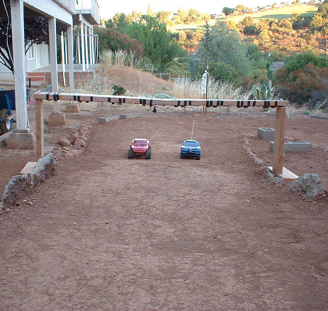
The transponders use infrared technology, An overhead bar is placed at the start/finish line approximately 24 inches above the track with sensor modules placed every 14 inches. When a transponder passes underneath
its ID will be sent to the PC. Many transponders can pass through simultaneously and all of them will be detected and counted.
I
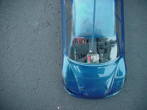
Transponders
Transponders are powered by the R/C receiver battery. The Transponder should be mounted as flat as possible. It may be mounted in the windshield area or by having a clear area in the front hood of the car it would be possible to mount the transponder there.
Testing
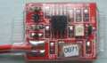
The Interface boards yellow LED will be on when a transponder is detected. The Transponders small LEDs will be on when the overhead sensors are detected.
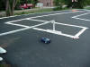
RC20 Video size 8MB in action indoors. A
beep will be heard every lap scored. Watch for the car that cart wheels
through the transponder detector and still scores a lap.
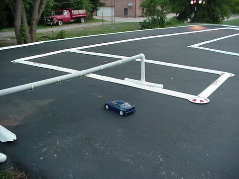
RC20 Video 4mb RC20 in action
outdoors in a parking lot with 1/10 nitro cars. The overhead detector bar
is near the van.
RC20 Video 14mb RC20 in action
with 1/12 scale 4 cell cars.
RC20 Video 4MB RC20 in action with 1/24 scale 4
cell Xmod cars
Download Software
version 2.0
Download Version 1
|

.jpg)
.jpg)
.jpg)